
PW615 VLJ Jet Engine / 3D diagram by Charles Floyd at
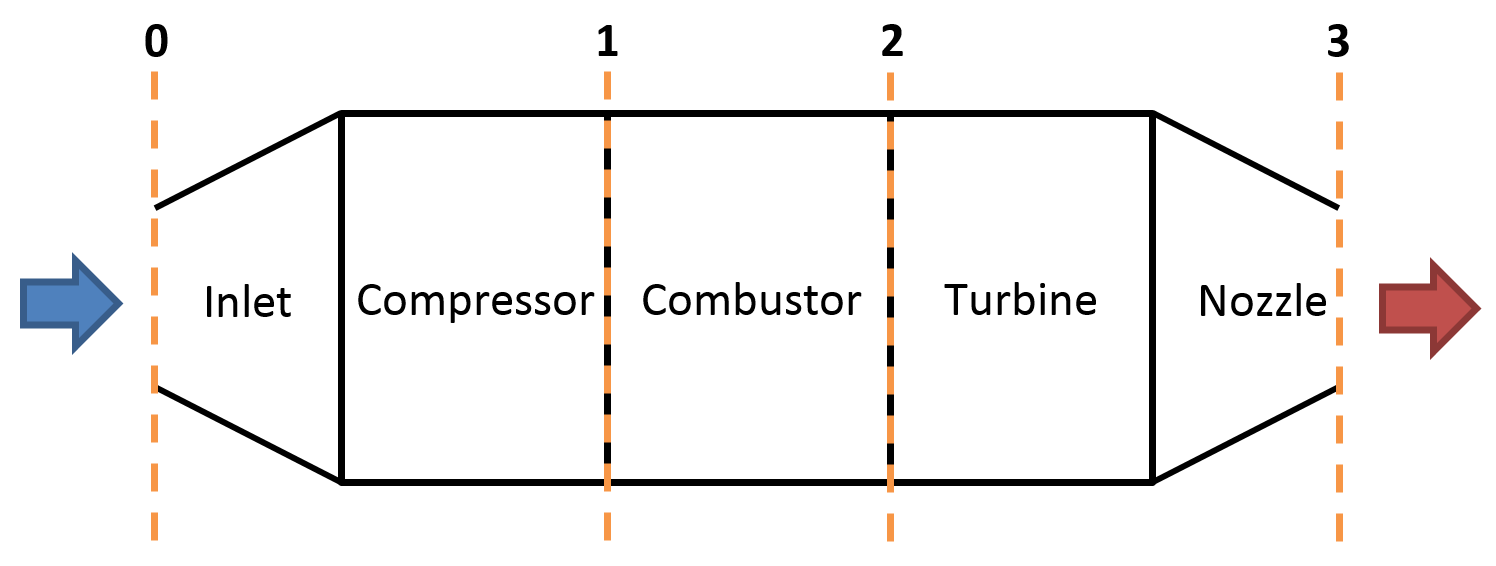
Jet engines are complicated pieces of machinery with many moving parts. To help understand how the machines work, engineers often draw simplified diagrams, called schematics, of the engine. The schematic is often a flat, two-dimensional drawing of the engine representing the important components.
Pulse Jet Engine Diagram My Wiring DIagram
A jet engine is a machine that converts energy-rich, liquid fuel into a powerful pushing force called thrust. The thrust from one or more engines pushes a plane forward, forcing air past its scientifically shaped wings to create an upward force called lift that powers it into the sky. That, in short, is how planes work —but how do jet engines work?
What is the difference between a turbofan and a turboprop engine
The diagrams above illustrate an ideal system. In reality, jet engines do not operate ideally. This means that the processes described above as isentropic or isobaric are not actually perfectly constant in entropy or pressure, resulting in slanted lines instead of vertical or horizontal lines.
Details 78+ turbojet engine sketch in.eteachers
A jet engine converts the liquid fuel into a strong force named as thrust. This force works for pushing the jet forward.
Definition > Jet engine
Jet engines move the airplane forward with a great force that is produced by a tremendous thrust and causes the plane to fly very fast. All jet engines, which are also called gas turbines , work on the same principle. The engine sucks air in at the front with a fan. A compressor raises the pressure of the air.

Airplane Engines (part 2) Jet Engines Back To First Principles
Below is an animation of an isolated jet engine, which illustrates the process of air inflow, compression, combustion, air outflow and shaft rotation just described. The process can be described by the following diagram adopted from the website of Rolls Royce, a popular manufacturer of jet engines.
Jet Engine Cutaway with Diagram CG Cookie
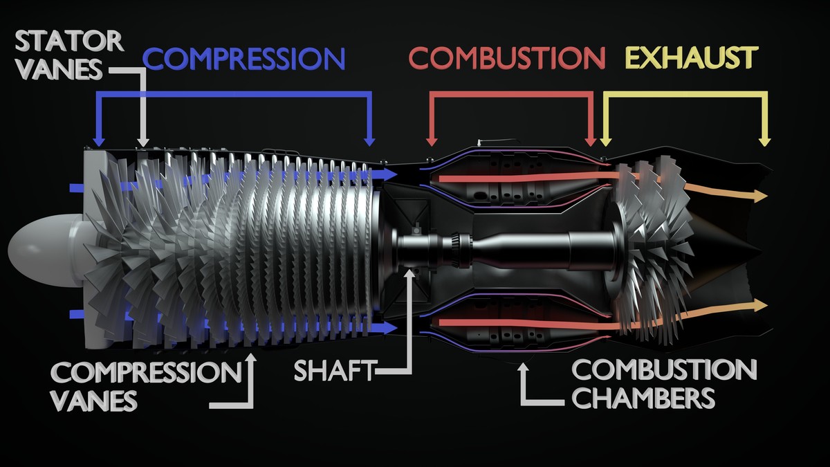
A gas turbine jet engine works by compressing air, mixing it with fuel, igniting the mixture, and ejecting the air behind the engine, creating a pushing force known as thrust. The engine does this using the basic principle of intake, compression, combustion, and exhaust, known as the Brayton cycle. This continuous cycle is what allows the.

The science behind how jet engines works?
At the front of a jet engine, a fan sucks in air. (If you look head-on at a jet engine on a passenger jet aircraft, you can see the blades of this fan.) The air is then retained inside the engine, where a compressor places it under pressure. The compressor contains more fans, all of which are fitted with blades and fastened to a shaft.

(a) Schematic diagram of a jet engine; (b) a turbine blade; (c) a
jet engine, any of a class of internal-combustion engines that propel aircraft by means of the rearward discharge of a jet of fluid, usually hot exhaust gases generated by burning fuel with air drawn in from the atmosphere. General characteristics The prime mover of virtually all jet engines is a gas turbine.
main components of jet engine Electrical Engineering Pics
An inside look at how jet engines work. Most modern jet propelled airplanes use a turbofan design, where incoming air is divided between a large fan and the.
How does a jet engine work? Brayton thermodynamic cycle and
By Jason M. Rubin. Jet engines create forward thrust by taking in a large amount of air and discharging it as a high-speed jet of gas. The way they're designed allows aircraft to fly faster and further compared to propeller-driven aircraft. Their development and refinement over the course of the last 65 years has made commercial air travel.
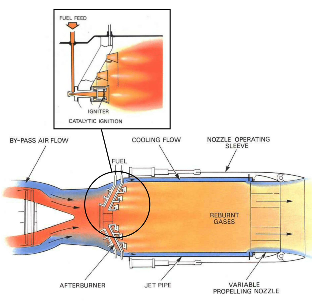
Jet Engine Design Afterburning Aerospace Engineering BlogAerospace
A jet engine is a type of reaction engine, discharging a fast-moving jet of heated gas (usually air) that generates thrust by jet propulsion.
Radial Aircraft Engine Diagram My Wiring DIagram
A jet engine is a highly complex piece of equipment with a straightforward job: to give an airplane the thrust it needs to fly.. This diagram shows the path of the air that bypasses the core.

Jet Engine
Media in category "Jet engine schematic diagrams" The following 146 files are in this category, out of 146 total. 3 types of combustion chamber.PNG 1,000 × 350; 58 KB 550px-Jet engine svg arabic.png 1,000 × 400; 244 KB Afterburner cut view model.PNG 850 × 350; 80 KB AirbreathingJetEngine.png 640 × 480; 6 KB Airintake duct.jpg 953 × 789; 137 KB

How a jet engine works Business Insider
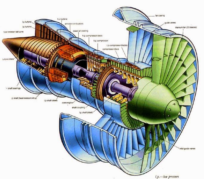
Diagram of a typical gas turbine jet engine. Air is compressed by the fan blades as it enters the engine, and it is mixed and burned with fuel in the combustion section. The hot exhaust gases provide forward thrust and turn the turbines which drive the compressor fan blades. (Photo credit: Wikipedia) 1.1 The Turbojet

Main components of a jet engine Download Scientific Diagram
Diagram of a typical gas turbine jet engine. Air is compressed by the compressor blades as it enters the engine, and it is mixed and burned with fuel in the combustion section. The hot exhaust gases provide forward thrust and turn the turbines which drive the compressor blades. 1. Intake 2. Low pressure compression 3. High pressure compression 4.